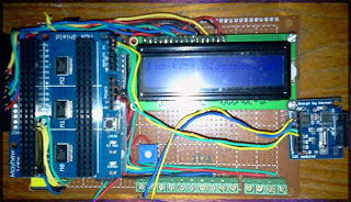
Setelah berekspreimen dengan line tracing, dilanjutkan dengan fire detector. Produk yang akan saya coba kali ini dari pabrikan china dengan seri YL-38. Sensor diterima tanpa datasheet tapi dari konfigurasi sudah secara jelas tergambar kalau produk ini mempunyai pin untuk power, 1 DO dan 1 AO. Prinsip kerja dari sensor ini adalah mendeteksi temperature dimana dia akan menghasilkan digital output sesuai dengan threshold yang diatur oleh potensiometer. Untuk program, bisa kita ambil referensi dari hobbycomponents seperti yang dibawah.
-------------------------------------------------------------------------------------------------------------------------------------------------------------
/* FILE: ARD_Flame_Detector_Sensor_HCARDU0024_Example.pde
DATE: 03/07/12
VERSION: 0.1
WEB: http://www.hobbycomponents.com
This is a simple example of how to use the HobbyComponents Arduino flame detection
module (HCARDU0024). The sensor has two outputs, an analogue output that is
dependent on how strong a flame is detected, or a digital output that will go high if
a flame is detected above a threshold set by the modules potentiometer.
This example program reads the status of both sensor outputs and outputs the result
to the UART.
SENSOR PINOUT:
PIN 1: Analogue out
PIN 2: Ground
PIN 3: +5V
PIN 4: Digital out
You may copy, alter and reuse this code in any way you like but please leave
reference to HobbyComponents.com in your comments if you redistribute this code. */
/* Select the input pin for the flame detectors analogue output. */
#define FLAME_DETECT_ANA A0
/* Select the input pin for the flame detectors digital output. */
#define FLAME_DETC_DIO 12
/* Initialise serial and DIO */
void setup()
{
/* Setup the serial port for displaying the status of the sensor */
Serial.begin(9600);
/* Configure the DIO pin the sensors digital output will be connected to */
pinMode(FLAME_DETC_DIO, INPUT);
}
/* Main program loop */
void loop()
{
/* Read the sensors analogue output and send it to the serial port */
Serial.print("Sensor Value: ");
Serial.print(analogRead(FLAME_DETECT_ANA));
/* Read the status of the sensors digital output and if it is high
then send an alert to the UART */
if (digitalRead(FLAME_DETC_DIO))
{
Serial.println(" FLAME DETECTED!");
}else
{
Serial.println();
}
}


